Arduino IR remote controlled Car
Categories
Arduino IR remote controlled Car
Created By

Roshan Baig
My name is Roshan, I am 13 years old and I am in 7th standard. My hobbies are horse riding, robotics, and computer programming.
About This Project
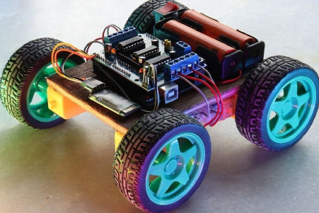
Arduino IR remote controlled Car
The project is arduino based project. I had spare time, so I made this.
This is the projects link
https://www.tinkercad.com/things/5xdxIXiPG4Y
and an old version
Components Required
- Arduino UNO
- LED Light bulb, Frosted GLS
- Texas Instruments Dual H-Bridge Motor drivers L293D
- 5mm LED :Red
- Through Hole Resistor , 1Kohm
- IR receiver
- IR Remote
- DC Motor, Miniature
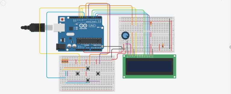
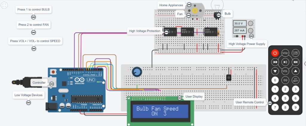
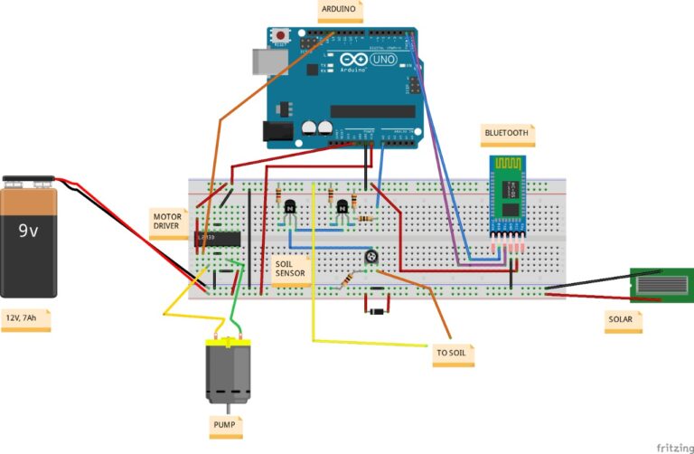
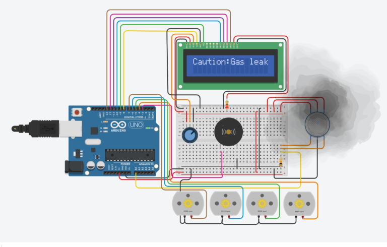
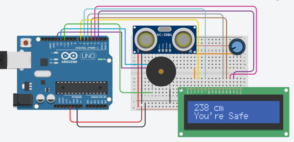
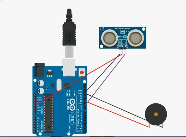
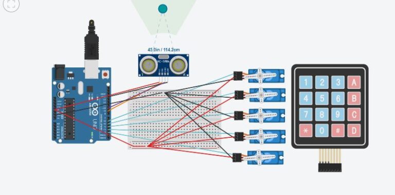
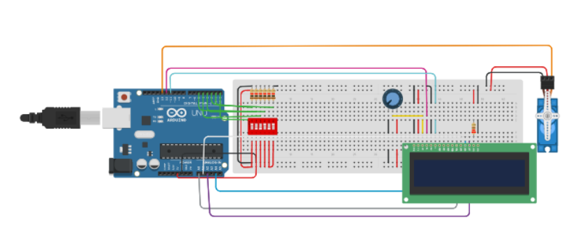
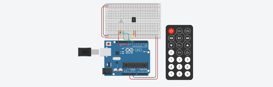
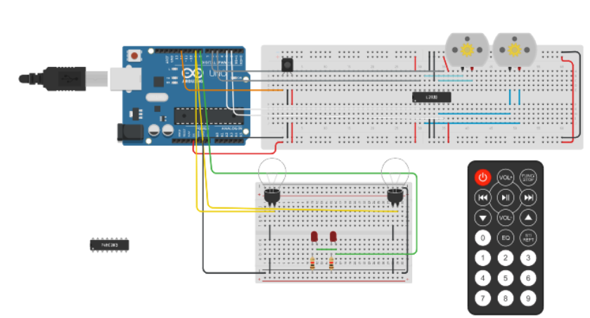
Schematics
In this image all the components with the connections are given
Code Of Project
#include <IRremote.h>
int receiver = 12;
int speed = 100;
IRrecv irrcev(receiver);
decode_results results;
void setup()
{
  pinMode(6, OUTPUT);
  pinMode(5, OUTPUT);
  pinMode(3, OUTPUT);
  pinMode(2, OUTPUT);
  pinMode(9, OUTPUT);
  pinMode(8, OUTPUT);
  pinMode(A0, OUTPUT);
  irrcev.enableIRIn();
}

void loop()
{
 if(irrcev.decode(&results))
 {
   irrcev.resume();
 }
  if(results.value == 16613503)
  {
    move_forward();
  }
  if(irrcev.decode(&results))
 {
   irrcev.resume();
 }
 if(results.value == 16621663)
  {
    stop();
  }
  if(irrcev.decode(&results))
 {
   irrcev.resume();
 }
   if(results.value == 16617583)
  {
    move_back();
  }
 if(irrcev.decode(&results))
 {
   irrcev.resume();
 }
 if(results.value == 16589023)
  {
    turn_left();
  }
 if(irrcev.decode(&results))
 {
   irrcev.resume();
 }
 if(results.value == 16605343)
  {
    turn_right();
 }
 if(irrcev.decode(&results))
 {
   irrcev.resume();
 }
 if(results.value == 16580863)
  {
    headlights();
 }
  if(irrcev.decode(&results))
 {
   irrcev.resume();
 }
  if(results.value == 16597183)
  {
    taillights();
 }
}
void move_forward()
{
  digitalWrite(5, LOW);
  digitalWrite(2, LOW);
  digitalWrite(6, HIGH);
  digitalWrite(3, HIGH);
}
void turn_right()
{
  digitalWrite(5, LOW);
  digitalWrite(3, LOW);
  digitalWrite(2, LOW);
  digitalWrite(6, HIGH);
}
void turn_left()
{
  digitalWrite(5, LOW);
  digitalWrite(6, LOW);
  digitalWrite(2, LOW);
  digitalWrite(3, HIGH);
}
void move_back()
{
  digitalWrite(6, LOW);
  digitalWrite(3, LOW);
  digitalWrite(5, HIGH);
  digitalWrite(2, HIGH);
}
void stop()
{
  digitalWrite(5, LOW);
  digitalWrite(2, LOW);
  digitalWrite(6, LOW);
  digitalWrite(3, LOW);
  digitalWrite(8, LOW);
  digitalWrite(9, LOW);
}
void headlights()
{
  digitalWrite(9, HIGH);
}
void taillights()
{
  digitalWrite(8, HIGH);
}